Welcome to Woodworks Made Easy

Practice any art, however well or badly, not to get money and fame, but to find out what's inside you.
--- Kurt Vonnegut

Pictures are meant to be self explanatory, and for visual clarity you may
click on each photo to enlarge. For older projects see Blog Archive. I don't specialize on a particular genre so there is quite a variety of projects for a number of different interests.

Even if you are not a woodworker but you like some or all of the projects, have your local crafts person make them for you from the ideas and photos you see here. For a particular project just click the specific title on the Blog Archive list (right side column below).

For anyone willing to learn or begin to do woodworking for the first time, please read first from the Blog Archive, "How and Where to Begin a Woodworking Hobby.

And it is not for men only. Read my note on "Women in Woodworking" from Blog Archive, April 2010.


click on each photo to enlarge


Monday, April 18, 2016

Mantle Plant Light Fixture

The previous owners of the house we live in now had the idea of creating an indoor planting area in a section of the foyer next to the front door and against the wall. It had to have cost extra to have that space through the foundation because the soil in it is all the way through the ground underneath.  Well, the garden did not work because of one little detail they didn't consider - light. Or, the idea perhaps was that there was going to be enough filtered light to come through the glass next to the door.  Anyhow, when we got the house a few plants that were in the soil were barely alive.

I decided to provide artificial lighting to the area by building a mantle up against the wall and install the light underneath it.  This was the least disruptive to the wall area.  There is a fireplace mantle in another area of the house that I wanted to copy, partly because from a certain viewing angle both mantles can be seen simultaneously. 

This is the model of the mantle design I made for the wall by the foyer.

The design called for a 1-1/2 inch half round for the edge as shown in the fireplace mantle. I purchased closet rods and split them lengthwise in half for the half round.

The challenge, of course, was how to split it at the table saw safely and accurately. I sandwiched the rod between two 2 X 4 lumber and drove a couple of screws to stabilize the rod during the ripping operation. It worked perfectly.

The next challenge was how to cut the miters on the half round.  This and the next photo shows how.


The finished mantle before painting.

I don't know how the fireplace mantle was attached to the bricks but I knew how this one was going to be secured against the wall.  The French cleat method is, in my opinion, the most ideal because this is a heavy structure for one person to install accurately and safely.

The French cleat allows for the easiest method of accurately placing and leveling a straight lighter rail against the wall.

I ran the necessary wiring for power from the other side of the wall where there was an outlet in the next room. As you can see there is no visible wire because the small hole was right behind the junction box. The junction box is where the timer will be plugged in.

I actually did this project a while back but since I was going to change the ballast for the florescent lamp when I decide to take the photos.

The unpainted portion shown in the foreground is the mating cleat to the one already attached to the wall.

For plants to grow the fixture needs a plant and aquarium light bulb.


Timer
This is quite heavy but the French cleat method makes it easy because the mantle will just slide into place from slightly up against the wall into the wall cleat like a wedge.


Tuesday, January 19, 2016

TV Cabinet Enclosure and Pocket Hole Joinery

Joinery is everything in woodworking and there are many varied ways to do it.  In cabinet making the speediest method is using pocket hole joinery.  Many purist woodworkers are likely not to use it but this is "Woodworking made easy" and as you shall see it can be fine woodworking when they're well hidden; and not an unpleasant sight even when exposed, as with the installation of the rear surround speakers up on the ceiling.

The original "TV stand" in the living area just had a table cabinet to support a television. The goal was to construct a cabinet around a flat TV and no wires should be visible in front.

The table cabinet had two solid doors so the first order of business was (1) cut out the left door and install a smoked glass where the receiver and other electronics that work on infrared frequency controls can receive the signal from the remote; (2) cut out a hole on the right door to expose the front of the sub woofer speaker.  A hand held jig saw did all the cutting.

The frame of the enclosure was constructed with stock white pine and put together with pocket holes (you may review previous blog on "Why pocket hole joinery".  I painted it to match the original table cabinet.

The right side is against a brick wall so it was left open. The left side has an access door to the back of the TV and to all the wiring behind.


An electronic fan was installed to evacuate heat generated by all the equipment below through holes drilled on the table top.
Indeed these do generate some heat.

The open top allows for heat from the TV to dissipate easily.

To hide the wires from showing up front I constructed narrow wall as shown and painted it with matching color of the cabinet and enclosure.

The wall in effect hides from the front view any wires behind the TV

And, no wires in front indeed. (Right, left and center speakers are at the enclosure itself.  The propagation of the sound from ten speaker sources (which includes the sub woofer) are managed by an on board computer that processes how much sound each speaker produces for five different listening locations, set up initially by five microphone placements (chosen typically by the seat locations where people sit). 


The two locations of the surround speakers were located at the back ceiling of the listening area and note the use of pocket holes to install the "post".

First, I installed a base plate (plywood) with a hole just enough for the speaker wires to go through from the ceiling. I constructed the post separately with pre-drilled four pocket holes. They were painted before installation. 


Monday, January 11, 2016

Expanding the Utility of the Krenov Sawhorse

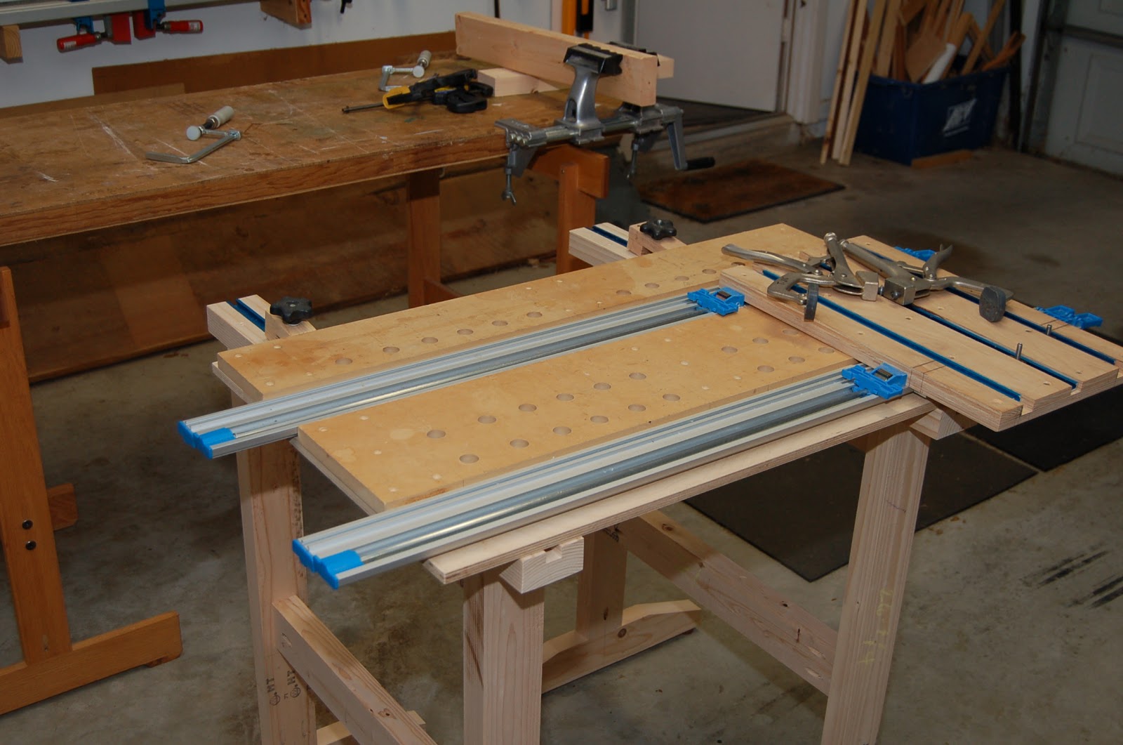
While the basic Krenov is already quite useful in a small work shop, "accessorizing" it adds more utility. The latest version of the Krenov 2G with the top rail laid flat allows for added capability when I routed out a 3/4 inch channel to accommodate T-tracks.  The T-tracks are flush to the flat surface so a double sided clamp can be installed as well for special but temporary applications.  A hefty work bench is typically considered a must-have in a work shop.  I have one but often, for much of what I do, it is either inadequate or way too much, which makes the space it occupies hard to justify.  I don't do a lot of hammering and the chisel work and hand planing I do are considerably light.  I do a lot of clamping for joinery and where mechanical fasteners are needed I use cordless drills. I find that 90 % of the operations do not necessarily require a work bench.  For sure I can do clamping and driving screws without needing a work bench. And often the Krenov sawhorse or a flat table are all I need. And with a small work shop I would like to set aside certain things when I don't need them and that way I do not encroach into the area where the car is (garage).  But if I have to I can always set up a temporary work area.  The Krenov fits the bill.

Refer to previous blog for constructing the Krenov 2G.


I keep repeating myself but one must agree that the Krenov sawhorses do not require much storage space. There are two pairs of them shown here.


An adjustable pair of clamps provide many work surface options; this is one example

If a small but  thick platform is needed, the adjustable clamps can secure it and more clamping options can be used.  The thick board can reasonably handle hammer blows and chisel work.

The double sided clamps allow the bottom section to clamp against the top rail while the top portion will have plenty of clamping options.

More clamping options


During construction of the Krenov 2, I made sure they were the same height as the "older" model to accommodate a wide board. A circular saw will cut this board safely.

The next photos are just examples of what the Krenov will support.  And don't forget how easy they were constructed and I assure the reader that the joinery provided by the pocket holes are very strong.


The tops here are light weight but incredibly strong and rigid.  Check the construction of the platform in "Torsion Box Construction" blog.

These tops will not even flex under the weight of standard table top power tools.


Saturday, December 26, 2015

A Japanese Tool Box


The Japanese tool box is most notably known for its cleverly designed distinctive lid (top cover) which is explained below.  I read somewhere that this design had been around for at least two hundred years, if not longer. Most boxes of this type - there are as many variations as there are craftsmen who make them - are typically longer, perhaps twice as long as the one I made here.  Those boxes are usually made to carry tools to a job site.  I only needed one to carry tools from the work shop to inside or around the house.  For the construction detail please see preceding blog, "Anatomy of a Japanese Tool Box"

Unlike most of the designs, I made mine a 2-compartment tool box. The seam is barely discernible because the two compartments were saw-cut from a single box (there is a tip on its construction from the previous blog).  As it turned out, the only feature I adhered to was the wedge locking system - which is what makes it a Japanese Tool Box.

Secret to the lid locking system: Slide one end towards the right and under the wide board; then slide it back towards the left under the narrower board.  The lid is now completely over the opening.  The next photo shows the wedge lock inserted in between the channel created as the lid is moved to the left.

 The second variation is in how I constructed the wedge.  Typically, it is a flat tapered wedge.  I cut the tapered wedge with the saw blade tilted slightly so there is no chance for it to pop out, once closed. 

The lid is positively shut and will  open only by retracting the wedge completely out of the channel.


Most household chores, if there is any drilling required, will likely need only the "lady" Festool drill.  I know the German manufacturer will not want to call it a "lady" cordless drill because they believe it has more than enough power to do the job that some bigger drills may be hard pressed to do.  

But the box will accommodate two drills in one compartment and hand tools in the other (top compartment)

Extra batteries included

When on a ladder, a smaller/lighter cordless drill is safer to use so whenever possible it has to be the tool of choice.